K2UA Rover.
[K5TR Home]
[DX Audio]
[Contest Stuff]
[YO Files]
[N5AU Tour]
[W5KFT Tour]
[6D2X TOUR]
[W2FU Rover Pictures]
Click on each image below to see a LARGER version.
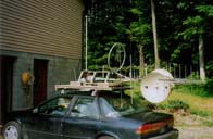 The K2UA rovermobile, just after the 1999 June VHF QSO Party, with
the antennas stowed for driving. The car is a 1994 Saturn SL2. The antennas
are supported by a short piece of Rohn 6 (ancient TV tower), which mounts to
a home-brew wooden rack made by W2FU. The rack attaches to the car with a
Yakima roof rack system. The rotator is a Ham-II, and the mast is an 8-foot
piece of aluminum pipe. The whole antenna platform, mast, rotator, etc,
fully loaded, weighs less than 100 pounds.
The K2UA rovermobile, just after the 1999 June VHF QSO Party, with
the antennas stowed for driving. The car is a 1994 Saturn SL2. The antennas
are supported by a short piece of Rohn 6 (ancient TV tower), which mounts to
a home-brew wooden rack made by W2FU. The rack attaches to the car with a
Yakima roof rack system. The rotator is a Ham-II, and the mast is an 8-foot
piece of aluminum pipe. The whole antenna platform, mast, rotator, etc,
fully loaded, weighs less than 100 pounds.
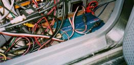 A close-up view of the power distribution for K2UA/R. Power comes in
to the inverter from the battery on a piece of 10-3 (with ground) UF-B house
wire about 10 feet long. Two wires are paralleled for positive, and the
other two for negative. The inverter chassis is grounded directly to the
body by a 1-foot piece of #12 wire. Everything except for one IF radio runs
from the 500-W inverter shown here. I got it from Damark for $63. But it
really need some output filtering.
A close-up view of the power distribution for K2UA/R. Power comes in
to the inverter from the battery on a piece of 10-3 (with ground) UF-B house
wire about 10 feet long. Two wires are paralleled for positive, and the
other two for negative. The inverter chassis is grounded directly to the
body by a 1-foot piece of #12 wire. Everything except for one IF radio runs
from the 500-W inverter shown here. I got it from Damark for $63. But it
really need some output filtering.
 And they call this wireless! Almost all of the equipment stacks up
on a couple of wooden shelves that sit on the passenger seat. Works great. I
added a few bungie cords for stability, but the whole thing tends to stay
put quite well. Next time I'll remove the seat and build a dedicated wooden
rack that will bolt into the car in place of the seat. In the current
configuration, it takes about three hours to get all the gear into the car
and hooked up, and just an hour to take it all out.
And they call this wireless! Almost all of the equipment stacks up
on a couple of wooden shelves that sit on the passenger seat. Works great. I
added a few bungie cords for stability, but the whole thing tends to stay
put quite well. Next time I'll remove the seat and build a dedicated wooden
rack that will bolt into the car in place of the seat. In the current
configuration, it takes about three hours to get all the gear into the car
and hooked up, and just an hour to take it all out.
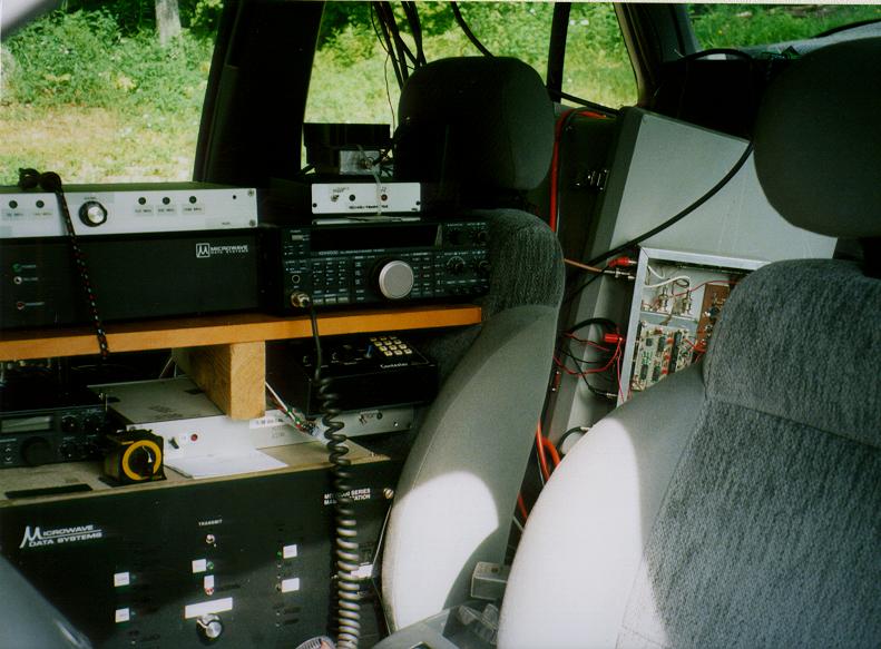
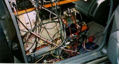
 A view of the equipment. The back seat contains the 222 transverter
(open cover) and the TWTA for 3.4, 5.7 and 10 GHz. The tube, a Siemens
RW-189, puts out 15 W on 3.4 and 5.7 GHz, and a couple of watts at 10.368
GHz, all for about a milliwatt of drive. It requires -24 V for power. The
feed lines exit the car through the back window.
A view of the equipment. The back seat contains the 222 transverter
(open cover) and the TWTA for 3.4, 5.7 and 10 GHz. The tube, a Siemens
RW-189, puts out 15 W on 3.4 and 5.7 GHz, and a couple of watts at 10.368
GHz, all for about a milliwatt of drive. It requires -24 V for power. The
feed lines exit the car through the back window.
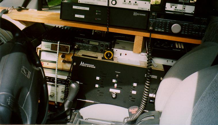
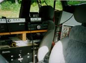
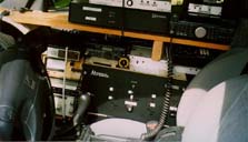 The driver's-eye view of the gear. The top shelf contains the
1296-MHz transverter, 28-MHz IF switch, and TS-690S (six meters plus 28-MHz
IF for 144, 222, 432 and 1296 MHz). The 432 transverter sits atop the
TS-690S. On the lower shelf, from left to right, are a stack containing the
2-meter transverter, rotator control box and the 100W 432 MHz amplifier. To
their right is a surplus 19-inch rack-mount cabinet inside which are the
transverters for 903, 2304, 3456 and 5760 MHz. The 10.368 GHz transverter
sits on top of the box, to the right of the 2-meter IF transceiver. All band
switching is done with a pair of rotary switches--one for each IF radio.
The driver's-eye view of the gear. The top shelf contains the
1296-MHz transverter, 28-MHz IF switch, and TS-690S (six meters plus 28-MHz
IF for 144, 222, 432 and 1296 MHz). The 432 transverter sits atop the
TS-690S. On the lower shelf, from left to right, are a stack containing the
2-meter transverter, rotator control box and the 100W 432 MHz amplifier. To
their right is a surplus 19-inch rack-mount cabinet inside which are the
transverters for 903, 2304, 3456 and 5760 MHz. The 10.368 GHz transverter
sits on top of the box, to the right of the 2-meter IF transceiver. All band
switching is done with a pair of rotary switches--one for each IF radio.
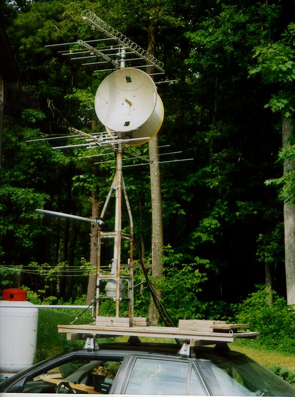
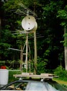 A view of the antennas in the operating position. There are six
antennas on the mast and one on the tower. See the next caption for a
description.
A view of the antennas in the operating position. There are six
antennas on the mast and one on the tower. See the next caption for a
description.
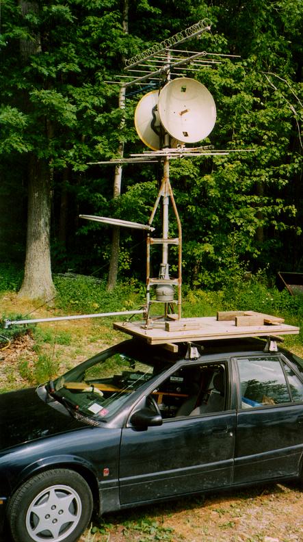
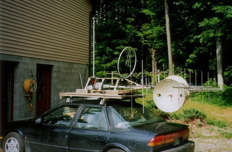
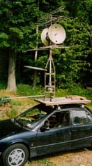 Another view of the antennas. From the top down are a 6-foot-boom
1296-MHz loop Yagi; the back 1/3 of an FO-16 for 222 MHz; a 903 MHz
commercial Yagi (dark blue--hard to see); a pair of 2-foot dishes,
back-to-back (one covers 10 GHz and the other has a triband feed for 2.3,
3.4 and 5.7 GHz); and a Cushcraft dual-band Yagi for 144 and 432 MHz. The
six-meter antenna is the loop bolted to the front tower leg. This photo also
shows the 4-foot steel gin-pole pipe mounted to the tower near the pivot
point. This provides the mechanical advantage required to raise the antennas
into the operating position (an easy one-person job).
Another view of the antennas. From the top down are a 6-foot-boom
1296-MHz loop Yagi; the back 1/3 of an FO-16 for 222 MHz; a 903 MHz
commercial Yagi (dark blue--hard to see); a pair of 2-foot dishes,
back-to-back (one covers 10 GHz and the other has a triband feed for 2.3,
3.4 and 5.7 GHz); and a Cushcraft dual-band Yagi for 144 and 432 MHz. The
six-meter antenna is the loop bolted to the front tower leg. This photo also
shows the 4-foot steel gin-pole pipe mounted to the tower near the pivot
point. This provides the mechanical advantage required to raise the antennas
into the operating position (an easy one-person job).
[K5TR Home]
[DX Audio]
[Contest Stuff]
[YO Files]
[N5AU Tour]
[W5KFT Tour]
[6D2X TOUR]
All text and photos are copyright 1997,1998,1999 by Rus Healy K2UA and George Fremin III - K5TR
Comments to [email protected]
 The K2UA rovermobile, just after the 1999 June VHF QSO Party, with
the antennas stowed for driving. The car is a 1994 Saturn SL2. The antennas
are supported by a short piece of Rohn 6 (ancient TV tower), which mounts to
a home-brew wooden rack made by W2FU. The rack attaches to the car with a
Yakima roof rack system. The rotator is a Ham-II, and the mast is an 8-foot
piece of aluminum pipe. The whole antenna platform, mast, rotator, etc,
fully loaded, weighs less than 100 pounds.
The K2UA rovermobile, just after the 1999 June VHF QSO Party, with
the antennas stowed for driving. The car is a 1994 Saturn SL2. The antennas
are supported by a short piece of Rohn 6 (ancient TV tower), which mounts to
a home-brew wooden rack made by W2FU. The rack attaches to the car with a
Yakima roof rack system. The rotator is a Ham-II, and the mast is an 8-foot
piece of aluminum pipe. The whole antenna platform, mast, rotator, etc,
fully loaded, weighs less than 100 pounds.